I want to run spi test by connecting spi1 and spi3 of jetson xavier nx board.
Before connecting spi1-spi3, I connected spi1’s MOSI-MISO (spi3’s MOSI-MISO) and tested with the spidev_test.c example to confirm that tx rx works well for both spi1 and spi3.
(Currently jetson xavier nx board has jetpack4.4 version installed.)
Here I have some questions.
How to do rx in spi slave?
Does an interrupt appear when data comes in?
Looking at the spi example (spidev_test.c), ioctl(fd, SPI_IOC_MESSAGE(1), &tr) is used to check tx and rx. Is this the only way to check rx?
If you check rx with ioctl(fd, SPI_IOC_MESSAGE(1), &tr), how do you know if the data has come in?
Are there any c++ examples of spi slaves?
For 1 and 2.
Configure as below. Add tegra124-spi-slave to the device tree.
Should be 1
open ssh terminal and start the spi slave first with following command
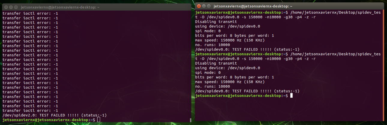
"./spidev_test -D /dev/spidev0.0 -s 150000 -n100 -g30 -p4 -z
In another terminal start the spi master with following command
“./spidev_test -D /dev/spidev3.1 -s 150000 -n100 -g30 -p4 -z”
(The photo shows’./spidev_test -D /dev/spidev0.0 -s 150000 -n10000 -g30 -p4 -z -r’, but When I used ‘./spidev_test -D /dev/spidev0.0 -s 150000 -n10000- g30 -p4 -z’ , the result was the same.)
[ 280.340212] spi-tegra124-slave 3230000.spi: Tx is not supported in mode 0
[ 280.340215] spi-tegra124-slave 3230000.spi: spi can not start transfer, err -22
[ 280.340301] spi_master spi2: failed to transfer one message from queue
There are a few things I’d like to ask in your answer.
Do you connect SPI1_MOSI<–>SPI3_MISO?
Why connect MOSI and MISO?
SPI1_MISO<–> Why doesn’t SPI3_MOSI connect?
Do I need to update the pinmux setting by changing from dt to slave means I have to flash again?
Can’t I do it in the following way?
(1) Activate spi1, spi3 in /opt/nvidia/jetson-io/jetson-io.py
(2) dtb decompile
—> sudo dtc -I dtb -O dts -o ~/ user-custom.dts / boot / tegra194-p3668-all- p3509-0000-user-custom.dtb
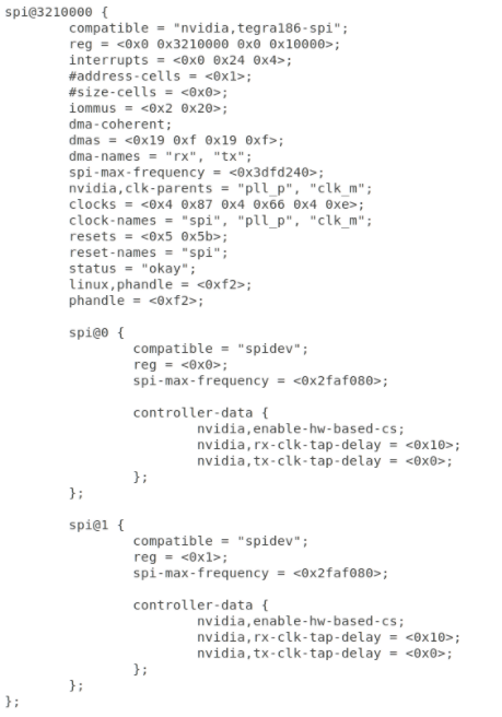
(3) Open the ~/ user-custom.dts file and change spi3(spi@3230000) to slave
(compatible = “nvidia, tegra186-spi” → compatible = “nvidia, tegra186-spi-slave”)
(4) dts compilation
—> sudo dtc -I dts -O dtb -o /boot/tegra194-p3668-all- p3509-0000-user-custom.dtb ~/user-custom.dts
(5) reboot jetson
(6) Change reg value using devmem2 (temporary)
(7) Connection: SPI1_MOSI<–>SPI3_MISO, SPI1_CLK<–>SPI3_CLK, SP1_CS0 ↔ SPI3_CS0 and SPI1_CS1<–>SPI3_CS1
(8) test
Where is the dt file? (Where should I change the spi3 slave?)
Where do I change the reg? Do I change it in my cfg (galen.cfg)?
Is the pinmux update method correct?
&&pinmux update method&&
(1) Jetson_Xavier_NX_Pinmux_Configuration_Template_v1.06 Set pinmux with .xlsm and create DT
(tegra19x-jetson_xavier_nx_module-gpio-default.dtsi, tegra19x-jetson_xavier_nx_module-padvoltage-default.dtsi, tegra19x-jetson_xavier_nx_module-pinmux.dtsi)
(2) Install Linux_for_Tegra with SDK Manager on Linux host PC
(3) Go to /Linux_for_Tegra/kernel/pinmux/t19x
(4) Import the dtsi( tegra19x-jetson_xavier_nx_module-gpio-default.dtsi, tegra19x-jetson_xavier_nx_module-padvoltage-default.dtsi, tegra19x-jetson_xavier_nx_module-pinmux.dtsi) file to the Linux host PC and create a cfg file.
----> python pinmux-dts2cfg.py --pinmux addr_info.txt gpio_addr_info.txt por_val.txt tegra19x-jetson_xavier_nx_module-pinmux.dtsi tegra19x-jetson_xavier_nx_module-gpio-default.dtsi 1.0>galen.cfg <------------
(5) Change galen.cfg to /Linux_for_Tegra/bootloader/t186ref/BCT/tegra19x-mb1-pinmux-p3668-a01
(6) Flash with sdk manager (or sudo ./flash.sh jetson-xavier-nx-devkit mmcblk0p1
Can you give me the source file of spi_test.txt that you gave me?
I want to know how to slave (functions used, interrupts, etc.)
When testing by connecting spi1(master)-spi3(slave), should I connect both SP1_CS0 <–> SPI3_CS0 and SPI1_CS1->SPI3_CS1?
Do you connect only one of cs0 or cs1?
Here you are told to run the command
./spidev_test -D /dev/spidev0.0 -s 150000 -n100 -g30 -p4 -z,
but the source code you gave me does not have the -g, -p, -z, -n options.
Also, how do I test master(spi1) -slave(spi3) with this code?
I need to run the slave first and then the master, but when I run the slave (/dev/spidev2.0) I get an error.
can’t send spi message: Invalid argument
Aborted (core dumped)
<<<<< dmesg >>>>>>
spi-tegra124-slave 3230000.spi: Tx is not supported in mode 0
spi-tegra124-slave 3230000.spi: spi can not start transfer, err -22
spi_master spi2: failed to transfer one message from queue
I want to test by connecting spi1(master)-spi3(slave)!
Master doesn’t want to know
An error occurs when executing the slave mode program.
I modified dt and reg value as you tell me to do, but when I run the program an error occurs.
can’t send spi message: Invalid argument
Aborted (core dumped)
<<<<< dmesg >>>>>>
spi-tegra124-slave 3230000.spi: Tx is not supported in mode 0
spi-tegra124-slave 3230000.spi: spi can not start transfer, err -22
spi_master spi2: failed to transfer one message from queue
Please tell me how to run the program in slave mode.
If you look at the error that occurs when you run the program, it seems that there is a problem with tx in slave mode.
So I want to see the source code.
can’t send spi message: Invalid argument
Aborted (core dumped)
<<<<< dmesg >>>>>>
spi-tegra124-slave 3230000.spi: Tx is not supported in mode 0
spi-tegra124-slave 3230000.spi: spi can not start transfer, err -22
spi_master spi2: failed to transfer one message from queue
And I have another question.
In the source code, ioctl(fd, SPI_IOC_MESSAGE(1), &tr) sends and receives data to tx,rx included in the tr structure.
Do you use ioctl(fd, SPI_IOC_MESSAGE(1), &tr) to send and receive data even in slave mode?
Why!!! Can’t I!!!
What else do I need to fix?
Or do I need to create a new driver for the slave?
Should I create a new test program?